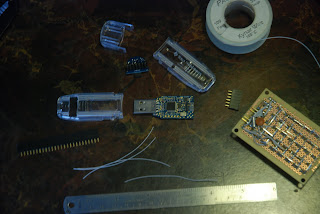
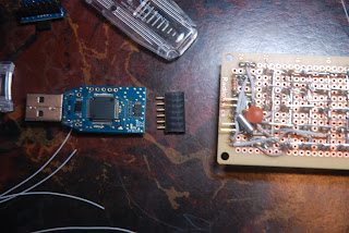
The first thing I did when I received my eZ430 was solder on some header pins to the target board. This target board has the F2013, but you can get packs of 3 F2012's for $10 from TI. To allow the pins to come out of the case I used my soldering iron (not a good idea!) to melt away the plastic. So now I can have the USB stick all closed up, but still have the F2013 connected to my circuit and the programmer/debugger at the same time. And to connect it to my circuit/breadboard I made a connecting cable from a ribbon cable laying around and some 14-pin IDC sockets.
Making the adaptor from IDC to DIP was a little more work than I thought it should have been. I used 4 sets of single inline headers, and in hindsight it would have been better to use two dual inline headers side by side. Solder the DIP-side first, then push the IDC-side headers through the PCB until the bottom of them are flush with the black pin holder, then solder up the IDC-side. That way, the black pin holders will hold the header pins perfectly perpendicular to the PCB in both the X-axis and Y-axis, and you will be able to put the IDC socket onto the pins. If you use single inline headers then the pins will fall over as soon as the solder melts (the way I did it) and you will have to find another way to hold the pins straight while soldering. Not fun.
So now I have means to program/debug the target board, and have it plugged into my breadboard ready for experimenting. But I also have a few F201x in the drawer and I would like to be able to program them as well! Now this is not as easy as it seems. Those with deep pockets would shell out $99 for an MSP-FET430UIF USB debugging interface, but I have a better, and cheaper idea (note that you wouldn't be able to use the cheaper Parallel Port debugging interface because it doesn't support Spy Bi-Wire and the F201x doesn't use JTAG). The programmer/debugger from the eZ430 is very similar to the MSP-FET430UIF, but it is dedicated to only Spy Bi-Wire. If you have looked at the programmer up close you will notice that the only way to access the programmer is with the tiny right angle pins (made by Mill Max but I forget the part #).
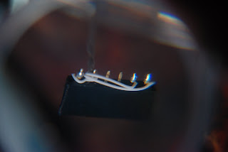
I tried every idea I had to use the eZ430 to program another chip (that wasn't a target board), but most never worked and a couple took some amazing acrobatics to get it to program. And this is each time you want to program the chip and/or debug. So I figured I should just solder directly to the eZ430 and have a breakout connector harnessing the Spy Bi-Wire interface (why didn't I think of that in the first place?).
I used some 30 gauge Kynar wire (what else!) and a 6-pin female 0.1" header (you can cut them off of a large strip). I previously built a charlieplexed 5x7 matrix driven by an F2013 and I used some right angle header pins to connect to Vcc, Vss, Reset, and Test. I chose their location based on the F2013's pinout, except Vcc is brought around and above Vss. I will follow this design for future projects that have Spy Bi-Wire (kinda like my own proprietary connection).
I made an SMD holder (I got the idea from work) out of an incense burner and a bent paperclip. This is indispensable while working with small PCB's and SMD components. Bend the paperclip so that there is some force pushing down on the PCB. Strip off 1-2 mm of insulation and solder to the pins using lots of flux, of course. Use lead-free if you care about RoHS, but I don't. Bend the wire to suit your style. I put the wires through the empty holes (used for initial programming of the debugger) so they can come out the hole on the top of the case (most likely intended for an LED).
I twisted the wires together to add some strength (I hope it doesn't interfere with the communications, but it hasn't complained yet) and I found that twisting all the way down to the PCB helped alot. I centered the wires underneath the hole in the case.
I am a fan of wire wrap and I find uses for it everywhere. You can pick up a wire wrapping tool from radio shack for around $6 or off ebay. This is all you really need, unless you were going to wire up a computer or something. I wire wrapped the Kynar wire (now you know why I used it!) to the female header as Vcc, Vss, empty, empty, Test, Reset to coincide with my charlieplexed matrix. I brought the wires up to the Vcc, Vss side so that it was easy to remember which way to plug it in. As a habit, I solder over the wire wrapped connections if I don't plan on taking it apart anytime soon.
Now I can get back to coding in CCS v4.


1 comment:
I'm now not certain the place you're gеtting your informatіon, hoωevег good topіс.
I must ѕpеnd ѕome time leaгning more or figuring out more.
Thanks for eхcellent infοrmation Ι ωas searchіng for this information for my misѕion.
Hаve a lοоk at my weblοg resіstor сolor codе calculatoг (Pass-drug-test-how-To.com)
Post a Comment